Your MEGAVISION 3D & TV-OUT Graphics Adapter comes complete with a host of software drivers and utilities which enable you to configure your adapter to suit most of today's popular applications. We will go into to detail on three of the main applications, Windows'95, Windows 3.1, DOS and Windows NT, however text files for installation of other application drivers can be found on the diskettes included.
5.1 - Driver Installation procedures on diskette
Driver installation procedures for the following applications are included on Diskette # 2.
5.2 - Windows '95 Driver Installation
The MegaVision 3D & TV-OUT Graphic Adapter is fully compliant with Windows'95 Plug & Play, and as such your system will recognize that this is a Trident 968x series VGA controller chip and assign a driver accordingly. However it is recommended that you install the drivers included on the diskette in this package, as they will be the most updated drivers available.
If you are REPLACING an existing graphic adapter with the VisioonXtra3D Graphics Adapter, then you must first set your 'Display Settings' back to 'Standard VGA'. You do this as follows.
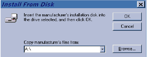
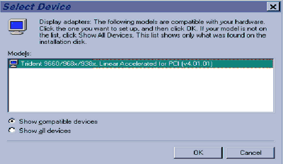
Once you have completed the above tasks, and installed the MegaVision 3D & TV-Out Graphics Adapter into your system, then you are ready to load the Trident ProVidia9685TM Drivers & Utilities. After turning on your system again follow these procedures for Windows '95 software installation.
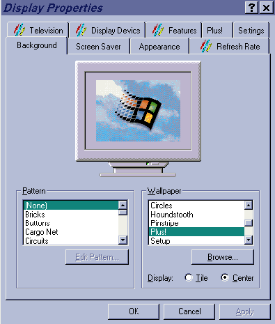
The MegaVision 3D Graphic Adapter now includes a setting within the Display Properties page called...
This control page allows the user to select features such as 'UnderScan' and 'OverScan', 'Interlaced' or 'Non-Interlaced', and to adjust the 'Screen Shift', of the television display
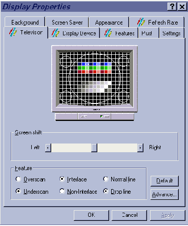
Screen Shift acts very much like the screen shift on most monitors. If the picture on your TV is slightly out of center then adjust this accordingly.
UnderScan is a unique software control which allows you to adjust the size of the computer's graphic, program or picture so that you are able to see the entire picture on your TV set. Therefore if you experience parts of your computer program (etc) out of the TV picture then choose this option.
OverScan works in the opposite way to UnderScan. By choosing this option, parts of the computer program (etc) will be out of the TV picture area and partially covered by the TV casing. You may wish to choose this option if you want to increase the picture size, and the partially covered area does not affect your application.
Interlace / Non-Interlace - If your television screen flickers excessively choose Non-Interlaced to reduce this affect.
Advance - By choosing Advance .. the following screen will appear.
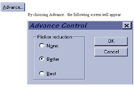
Flicker Reduction. To further reduce any possible flicker reduction check 'Better' or 'Best'
Display Properties.
This screen allows you to switch between CRT Mode and output-to-TV mode
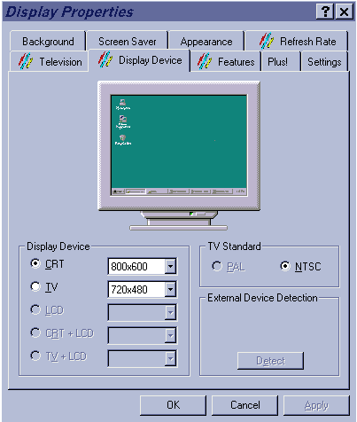
TV Standard is set automatically according to the jumper settings of JP14, JP15, JP16, JP17.
Display Device lets you select whether output is to CRT Monitor or to TV, and it further lets you select the resolutions of both.
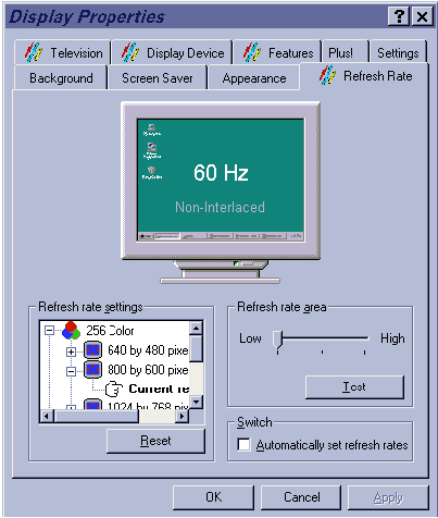
Refresh Rate
The refresh rate is the rate at which the screen re-draws the graphic data (or 'refreshes' that data). This can depend on the type of monitor you are using, however there is a convenient TEST button which will automatically test your monitor against the settings you make.
5.3 - Windows 3.1 Driver Installation
The Graphic installation procedure TINSTALL supports a simple six-step installation procedure for the display driver program, the power management program and the Uninstall program.
To use TINSTALL follow the 6 steps below...
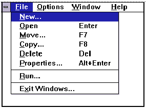
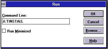
A menu will appear, presenting a choice of Express of Custom Installation
Express installation is quick and decision free. Display drivers will be copied into the TRIDENT.HGI directory and Utility files will be copied into the TRIDENT.UTL directory. Once all files are copied, a program group called DISPLAY DRIVER AND UTILITIES will be created.
Custom installation allows control over file storage and in what program group the icons are placed. The first dialog box that appears shows the default directory to which the display drivers will be copied. To change the directory name select the default name, delete it and then enter the desired directory name. Once the desired directory name is selected, continue the installation procedure by selecting CONTINUE, or by pressing ENTER. The next dialog box displays a summary of where files are stored. Select CONTINUE to copy the drivers and utilities files. When all files are copied, the program will present a choice of program groups where the icons will be created. Create a new group to place the utility icons or select from pre-existing groups (e.g. main, applications, accessories etc.).
When all necessary files are copied and a group name is selected, the TINSTALL program will create four icons:
NOTE: Different "display driver set" versions cannot be installed to the same directory name.
"Display driver sets" of the same version number ( e.g. UH6.x ) will replace the existing one.
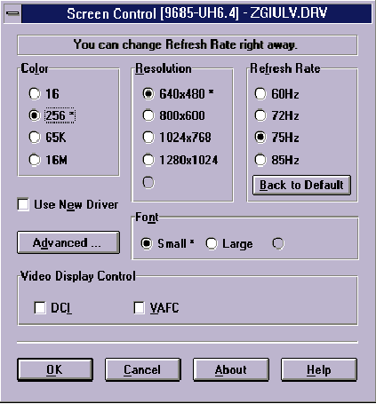
5.3. 1 - SCREEN CONTROL
The Screen Control panel contains controls for setting screen resolution, color depth, font size, refresh rates. Not all combinations of screen resolution, color depth, font size and refresh rate are attainable.
Color depths of 16, 256, 64K, or 16.7M colors can be selected by clicking next to the desired option. Color depth determines the number of colors that may be simultaneously displayed on the screen. The selected color depth determines the possible resolutions.
Screen resolutions of 640x480, 800x600 or 1024x768 can be selected by clicking next to the available options. The virtual screen size is automatically adjusted to be at least as large as the selected screen resolution.
Available refresh rates are dependent on the selected color depth and resolution. The "Back to Default" option is used to reset the refresh rate to the factory default value in case your monitor does not support a high refresh rate.
Configuring the Display Driver
Video Applications
Video playback on the MegaVision 3D & TV-Out Graphics Adapter can be achieved with the installation of most MPEG software decoder or with MS Video for Windows 1.1e Runtime or later; however, better display quality and playback performance can be achieved by installing the Trident Display Control Interface (DCI) driver since this driver utilizes the Accelerated Video Engine of the ProVidia9685( chip.
While MPEG software decoders are available from third-party software providers, Trident's DCI driver may be enabled after display driver has been installed; it may be enabled or disabled by checking the box next to "DCI" option under Video Display Control in Trident's Screen Control program.
Microsoft's Video for Windows 1.1e Runtime or third-party MPEG software decoder need to be installed to take advantage of Trident's DCI driver. Installation procedures as well as installation software for Microsoft Video for Windows 1.1e can be found in the Microsoft Video for Windows 1.1e software package which may be purchased separately. Installation procedures for third-party MPEG software decoder is usually found in the README.TXT file of the perspective MPEG software decoder diskette.
Once Windows is re-started after Microsoft's Video for Windows 1.1e or third-party MPEG software decoder is installed, go into the "Accessories" program group to run "Media Player". Trident DCI driver is now activated and the line "Video for Windows" will now appear under the "Device" option. Select "Video for Windows" to run any files with AVI extension. Select the driver installed by third-party MPEG software decoder in "Media Player" to run files with MPG or DAT extension.
Installation Verification
If the desired performance is not achieved after the DCI driver is enabled, the following procedure verifies if Trident's DCI driver is installed correctly.
For AVI (Audio Video Interleave) video playback, better performance requires at least Intel 486DX2 class CPU and double speed CD player. For MPEG software decoders, better performance requires at least PentiumTM class CPU and quad speed CD player.
Advanced Features (Virtual Screen Control)
The advanced features of the program is accessed by pressing ALT + D or by clicking on the box marked Advanced.
This action opens up an extension of the Main Panel that presents the following features:
Standard display resolutions are 640x480, 800x600, 1024x768 or 1280x1024. The amount of display memory used depends on the selected resolution and color depth. For resolutions of 640x480, 800x600 and 1024x768, there is a substantial amount of display memory left unused. The Virtual Screen features takes advantage of this unused memory by "expanding" the display area into the off-screen area.
Virtual Screen Control allows the user to make effective use of a display screen larger than the standard 640x480, 800x600 or 1024x768, and the standard resolution is the center of the screen. The user can "pan" around the larger Virtual Screen area by the use of a standard mouse or a set of "HOT KEYS." For example, it is possible to select a resolution of 640x480 and set the Virtual Screen size to 800x600. Thus, the 640x480 screen sits at the center of a 800x600 matrix, and the user can "pan" through the entire 800x600 matrix in a 640x480 window.

Panning allows traversing a larger screen through a smaller window.
 VIRTUAL SCREEN AREA
 ACTUAL DISPLAY AREA
The Customize feature provide functions to customize the virtual screen, as shown below.:
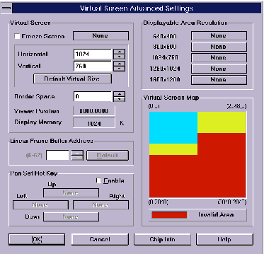
Freeze Screen
The Freeze Screen option is used to disable the panning feature, giving the illusion of a frozen screen but keeping other virtual screen functions available. Hot key functions are available for this feature.
Linear Frame Buffer Address
The Linear Addressing driver will automatically detect the system's memory size and sets the frame buffer to an unused area above the system memory (VL bus card only). The Linear Frame Buffer Address setting is useful in avoiding conflicts with Windows applications which use the same linear frame buffer address as the Display Driver. Addresses between 18 and 63 MB can be selected. If there is no conflict, the default setting is highly recommended.
Border Space
The Border Space option is used to set up a border (thickness measured in pixels) within the Displayable Area, which is used as a marker for panning the screen, i.e. when the cursor hits against this border, screen panning occurs .
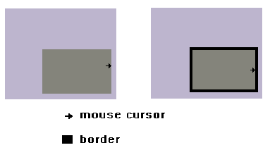
NOTE: Border space sets up a transparent border (black area) on the display area, that is used as a threshold to start panning the virtual screen.
Pan Set Hot Key
Hot keys can be set up to pan the virtual screen left, right, up and down. The feature has to be enabled first by clicking on the ENABLE box, before hot keys can be selected.
Once all selections are made, click on OK or press ALT + O to exit the advanced setup.